E2208: Plasma won't ignite
Issue
Plasma will not ignite and error E2208 or E2209 is reported
The E2208 error is generated when the plasma fails to light but no known interlock has been triggered during the failure to ignite the plasma. When this error is encountered, the following steps can be taken in order to try and determine what the source of the ignition failure is:
Environment
- iTEVA
- Qtegra
- ICP-OES
- iCAP 6000 Series
- iCAP 7000 Series
Resolution
1) Igniter Wire
a) Is the igniter wire orientated correctly? The igniter wire should be perpendicular to the torch and butted up against the torch.
b) Is the tip of the igniter free from corrosion? The igniter wire is a copper core surrounded by a rubber sheath. The tip of the igniter should be shiny copper. If there is corrosion present on the tip of the igniter wire, this should be cleaned off using something like sandpaper or the igniter wire should be trimmed back by about an 1/8” in order to expose new copper.
2) Is the Spray Chamber draining effectively?
Check to make sure that that there is no liquid backing up into the spray chamber. If enough liquid accumulates in the spray chamber, it can cause droplets to make there way into the torch and prevent the plasma from igniting. If there is liquid backing up in the spray chamber suspect a clogged waste line, peristaltic pump tubing for drain needs to be replaced or tension on the tubing needs to be adjusted, etc. Also, if liquid has migrated into the torch, disassemble and allow the torch components (quartz tube and torch holder) to air dry overnight to ensure that no liquid is left. If you have a spare torch and holder, they can be installed to continue troubleshooting in the meantime.
3) Sample Introduction Components
Have any sample introduction components been changed, i.e. torch, o-rings, etc either right before or since the issue started occurring? If so, did you use Thermo Scientific parts?
a) If components have been changed since the last time the plasma successfully ignited, then the components which have been changed could be defective. Please replace them with the original component and see if the plasma ignites then.
b) If no components have been changed since the plasma ignition issue started occurring, it would be a good idea to troubleshoot the torch. Namely, it would be a good idea to replace the torch, injector and torch holder with new parts and see if the plasma ignites then. Please make sure you use genuine Thermo Scientific parts for these components.
4) Ceramic Torch
Are you using a ceramic torch aka the D-torch? If so, is the outer tube lined up correctly so that the ignition pad is in the correct place? Have you tried another ceramic torch or cleaned the one in use? If it is still not lighting, please insert the default torch (metal body and quartz torch) and try lighting the plasma. Does it light? If it does, then suspect the D-torch as the source of plasma ignition failure.
5) Torch connection to Torch Holder
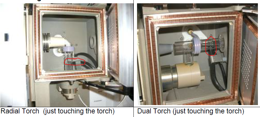
Has the torch been inserted properly into the torch holder, see Figure 1? The target painted on the torch should be seated in the recess at the top of the torch holder.
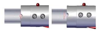
Figure 1: The torch is inserted properly in the image on the left but has not been pushed down far enough in the image on the right.
6) Injector Tube Holder connection to Torch Holder
Is the top of the base of the injector tube holder flush with the base of the torch body, see Figure 2?
It is possible for the center tube holder to be cross threaded when screwing it into torch holder. Therefore, please verify that the injector tube holder is seated flush throughout the entire circumference with the torch holder. There should be no gap anywhere between the torch holder and the injector tube holder.
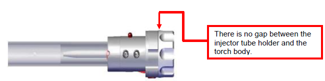
Figure 2: Injector tube holder mounted correctly in the torch body
7) Torch holder O-rings
Are the o-rings located on the coolant and auxiliary gas inputs to the torch holder in place, see red box in Figure 3? Please verify that all the o-rings are in place and replace if the o-ring looks worn.
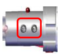
Figure 3: Torch holder o-rings
8) Chiller Water
When is the last time the chiller water was changed? It is important that the chiller water is changed at least once per year. If you are running the instrument 8 hours a day / 5 days a week or more, the chiller water should be changed every 6 months. If the chiller water needs to be changed, please do so using a solution of 2% corrosion inhibitor and 98% distilled water (not tap or 18 megaohm deionized water).
9) Leaks in Sample Introduction System
Check the sample introduction for leaks by removing the spray chamber, sealing the ball join with parafilm (scotch tape will also work), placing the clip on the ball joint to secure the parafilm and then try lighting plasma. If it lights, a leak should be suspected somewhere in the sample
introduction system before the ball joint (i..e. o-rings which seal nebulizer in spray chamber, nebulizer gas line, etc.
10) Check the Load Coil Alignment
Run a 1mm Allen wrench or wooden Q-tip around the space between the coil and outer quartz tube and see if resistance is encountered anywhere. If it is, suspect that the coil is touching the torch in that area. Gently bend the coil in a manner so that the coil is no longer touching the
torch and re-check spacing.
The distance between the load coil and the inner quartz tube should be 1/8” or appr. 3mm. If it is
not, gently bend the coil so that this distance is met.
11) Argon Gas
Did the plasma ignition issue start happening after the Argon gas supply changed? If so,bad Argon gas should be suspected and the gas should be replaced.
12) Leaks in Gas Line
Are there any leaks in the argon line running from the argon supply to the instrument? All junctures should be especially scrutinized. This can easily be done by dispensing about a quarter sized amount of liquid soap into a beaker, filling the beaker with about 20 mL of DI water and then using a 1” paint brush to whip the solution so that suds appear. The suds (none of the liquid) can then be applied using the paint brush to all of the junctures in the Argon line to the instrument. If the bubbles start to get bigger at any juncture, a leak should be suspected and subsequently corrected.