Troubleshooting E9000 Error in iTEVA and Qtegra for iCAP 6000-7000 Series
Issue
Plasma goes out after ignition and error E9000 is generated after doing so
Environment
iCAP 6000 Series
iCAP 7000 Series
Resolution
The E9000 error is generated when the plasma goes out but no known interlock has been triggered to cause the plasma to do so. When this error is encountered, the following steps need to be taken in order to determine where the source of the plasma going is:
1) Have any sample introduction components been changed, i.e. torch, o-rings, etc either right before or since the issue started occurring? If so, did you use Thermo Scientific parts? If components have been changed since the last time the plasma successfully ignited, then the components which have been changed could be defective. Please replace them with the original component and see if the plasma stays lit.
If no components have been changed since the plasma started going out, it would be a good idea to replace the torch, injector and torch body and see if the plasma stays lit then. Please make sure you use genuine Thermo Scientific parts for these components.
Are you using a ceramic torch? If so, have you tried another ceramic torch or cleaned the one in use?
2) When is the last time the chiller water was changed? It is important that the chiller water is changed at least once per year. If you are running the instrument 8 hours a day / 5 days a week or more, the chiller water should be changed every 6 months. If the chiller water needs to be changed, please do so using a solution of 2% Havoline and 98% distilled water (1-3 Mohm - NOT tap or 18 megaohm deionized water).
3) Is the Spray Chamber draining effectively?
Check to make sure that that there is no liquid backing up into the spray chamber. If enough liquid accumulates in the spray chamber, it can causes droplets to make there way to the plasma and extinguish it. If there is liquid backing up in the spray chamber suspect a clogged waste line, peristaltic pump tubing for drain needs to be replaced or tension on the tubing needs to be adjusted, etc.
4) Check the sample introduction for leaks:
a) Are there any leaks in the sample path? This is typically easily observable by air bubbles being present in the path. However, if you don’t see any air bubbles in the path, sometimes it is good to purposely introduce some air bubbles into the path by for example raising the sample probe, waiting 2 seconds, reinserting sample probe into solution and so on, in in order to observe how fluid the motion of the sample is (no hesitation or jerkiness).
b) Is there an air leak in the neb gas line from the gas box to the nebulizer? This can be checked by snooping the fittings on either side of the line and also slightly bending the tubing to make sure it is still flexible and that there are no cracks in it.
c) Is there a leak in the channel in which the nebulizer is inserted into the spray chamber? When you try to remove the nebulizer from the spray chamber there should be some resistance in doing so. If there is not, it is possible that the spray chamber o-rings are worn and need to be replaced.
d) The nebulizer may have become inefficient. When this happens the spray pattern can look normal. The only way to truly test this is to put a new nebulizer in.
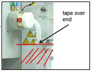
If it doesn’t take long for the plasma to go out upon ignition, another way to check the sample introduction for leaks or other issues is to by removing the spray chamber, taping over the ball joint, lighting plasma and observing if the plasma continues to go out.
5) Check the load coil alignment:
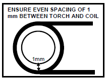
a) Run a 1mm Allen wrench or wooden Q-tip around the space between the coil and outer quartz tube and see if resistance is encountered anywhere. If it is, suspect that the coil is touching the torch in that area. Gently bend the coil in a manner so that the coil is no longer touching the torch and re-check spacing.
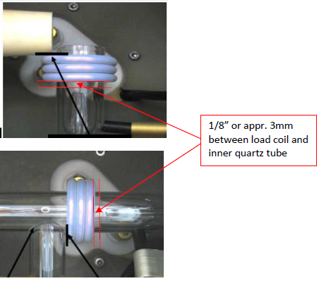
b) The distance between the load coil and the inner quartz tube should be 1/8” or appr. 3mm. If it is not, gently bend the coil so that this distance is achieved.
6) Are there any leaks in the argon line running from the argon supply to the instrument?
All junctures should be especially scrutinized. This can easily be done by dispensing about a quarter sized amount of liquid soap into a beaker, filling the beaker with about 20 mL of DI water and then using a 1” paint brush to whip the solution so that suds appear. The suds (none of the liquid) can then be applied using the paint brush to all of the junctures in the Argon line to the instrument. If the bubbles start to get bigger at any juncture, a leak should be suspected and subsequently corrected.