Time Resolved Setup Screen
Issue
A quick description of the various cells in the Setup Screen and what to consider when setting:
Environment
- Nicolet iS50R
Resolution
Spectral resolution - set to the minimum value necessary, as higher resolutions take
longer to collect and will be noisier. For testing we normally use 32 wavenumber.
Points before peak - Set this to the minimum value (64). This is called a single-sided collect. A double-sided collect requires more data points and will take longer to collect.
SSP - Must be set to 2 for mid-IR. Could be set to 4 or 8 if optical filters (114-725700 and 114-727500 respectively) are used to reduce the bandwidth.
Input Range - Active only if a Gage board is installed in the PC. Use the Auto setting for most experiments. OMNIC TRS software will change the input range of the Gage board automatically during the collect for improved signal to noise.
Settling time - Time after the step for the detector to stabilize (varies with the type of detector used, see SST Help for typical values).
Settling factor - a multiplication factor that is multiplied times the settle time for the 64 points around the centerburst (see SST Help for typical values).
Phase calculation - Use Each IFG, see SST Help in Omnic for more information .
Survey Scan - normally checked unless there is no (or very small, <10mv) centerburst. A survey scan which does not find the centerburst may start stepping in the wrong place.
Collect static IFG - normally checked. The static interferogram is collected while the moving mirror is stopped. Normally the DC output of the TRS detector is connected to the A input on the Nexus 870 cover to collect the static interferogram.
Add static IFG to TRS IFGS - normally unchecked, see SST Help in Omnic for more information.
Use spectrometer digitizer - If a Gage board is installed in the PC this option will be available. When this is checked, the B input will be the dynamic interferogram. The spectrometer digitizer will provide a better signal to noise spectrum than any of the Gage boards because the OBC has a 16 bit digitizer. However, it can only be used for slow experiments because the digitizer is 100kHz or 0.1 MS/s compared to the slowest current Gage digitizer which is 50MS/s.
Static avg. time - This is the time that TKDA is low. A longer static averaging time improves the signal to noise of the static spectrum at the expense of a longer collect time. This is the background using the DC output of the TRS detector.
Post-trigger delay - This is a delay after TKDA goes high before the first sample is taken by the Gage board (or internal digitizer).
Trigger interval - This parameter is calculated by OMNIC based on the settings of the other parameters. If the message missing trigger appears during a TRS collect increase this number.
Number of scans - usually set to 1, but more can be selected, see SST Help in Omnic for more information.
Number of triggers per step - Only active on an 870 with version 7.09 or greater firmware. Reduces collection time by allowing multiple experiment triggers while stopped at a fringe. (requires a Gage board).
Number of Samples - determines the number of dynamic (AC) interferograms collected (sample times).
Initial Dwell - determines how often a sample point is taken. The maximum speed is determined by the Gage board used. For example a Gage 12100 board has a sampling rate of 100MS/s. The time spacing is the inverse of 100 MSs or 10 ns
Points averaged - If the initial dwell parameter above is not set to the maximum speed available, additional points can be taken and averaged to improve the signal to noise ratio of the spectrum.
Linear or Logarithmic - Usually set to Linear, see SST Help in Omnic for more information.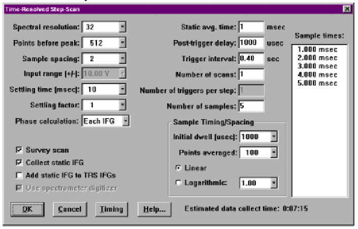
Attachment(s)
| File | Last Modified |
|---|---|
| TRS Setup Screen.jpg | May 31, 2022 |